The practical answer.
Inspect a cylindrical cell’s insulating surfaces against its approved drawing and again after the parts that can damage them have been fitted. Define the sleeve and terminal surround, check the assembled relationship to the carrier and conductive hardware, and route suspect cells through the documented material review procedure.
- Compare the approved individual cell part number and drawing.
- Capture where tooling, carrier ribs and electrical hardware meet the cell.
- Use separate records for incoming condition and process-induced damage.
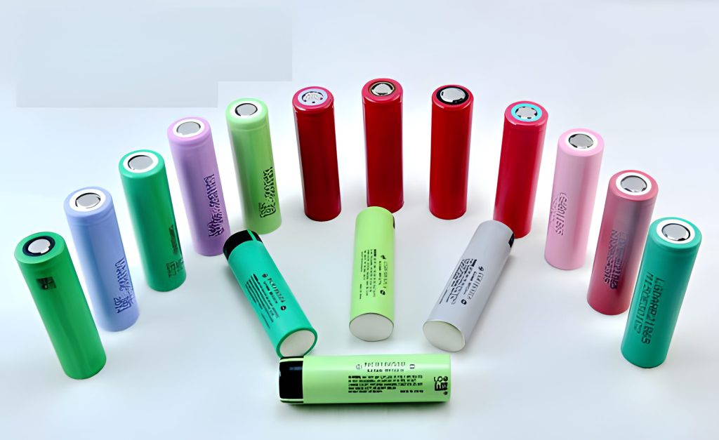
Mark the interfaces before designing a receiving gauge
Start with the drawing for the selected cell. Create a marked view that shows the positive terminal, the shoulder around it, the intended insulating coverage and any exposed surfaces permitted by the design. Ask the supplier to identify the electrical potential of accessible metal surfaces and which parts may be used for fixturing. A drawing for a different format can look similar and still put the insulating boundary or terminal land in another position.
Jetray’s cylindrical selection materials organize cells by format. The catalogue links below illustrate different formats and applications for a sourcing conversation. Set inspection limits with the selected component drawing and the actual carrier or busbar assembly. Ask for the allowed sleeve condition, dimensional limit and disposition method in writing.
Trace how the cell moves into the carrier
Look at the cell through unloading, orientation, insertion and movement to the interconnect station. Mark the surfaces that touch the wrap at each step. A carrier can have sufficient clearance when the cell is seated while the insertion lead-in still scuffs the sleeve. Use trial assemblies at the worst credible combinations of cell envelope and fixture variation. Document where rubbing or contact marks appear and whether the contact point moves when parts are assembled in the opposite allowable orientation.
Inspect the cell and carrier together before adding the busbar. A parting line, clip, edge or handling tool may be visible only before the next part covers it. Choose a view and lighting that give inspectors a repeatable look at that location. A photo with the carrier revision, orientation and marked area can make a decision consistent between shifts.
Review the top-end boundary with conductive parts fitted
Check what happens at the shoulder after the interconnect and any insulating spacer are installed. An apparent clearance on a drawing can disappear when a busbar is moved within its hole tolerance or when a spacer is installed off center. Review maximum permitted motion of the interconnect and the actual position of nearby fasteners. Use approved drawings and a controlled engineering trial for these checks.
Murata’s product guidance describes cylindrical lithium-ion cells as components intended to be embedded with appropriate protection in finished products. LG Energy Solution’s handling guidance discusses correct polarity, mechanical damage and contact with conductors. Treat these sources as background for the system review and follow the approved procedure for the selected cell and assembly.
| Checkpoint | Question to answer | Useful record |
|---|---|---|
| Receiving | Does the approved cell arrive with the expected coverage and condition? | Lot identity, drawing revision and approved inspection criteria |
| Carrier trial | Where does the fixture load or rub the cell during insertion? | Marked contact view and fixture revision |
| Interconnect trial | Can a shifted conductive part reach an unintended metal surface? | Reviewed stack-up and documented worst-case geometry |
| Release review | Was a cell, sleeve, tooling or interconnect change introduced? | Change record, affected lots and disposition authority |
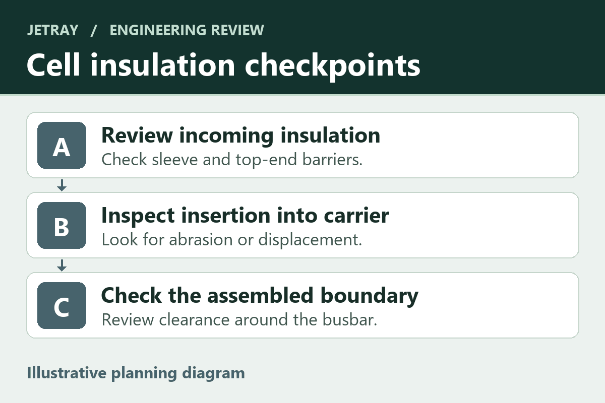
Contain a defect without making the next lot harder to trace
Record the location of an unexpected tear, dent, displaced insulating part or exposed surface before further handling. Keep suspect material out of the production flow under the organization’s approved battery handling and nonconformance procedure. Separate a suspected incoming condition from damage first observed after carrier insertion. That distinction helps engineers investigate supplier variation or tooling without attributing a cause too early.
An RFQ for a new cell can request the drawing, packaging method and permitted variations along with the usual electrical data. Add a process review when the order specifies a different supplier or packaging orientation. The objective is to retain evidence that the component and the assembly process preserve the intended electrical separation.
Make the observation consistent between inspectors
Ask two trained inspectors to review the same reference views under the proposed line conditions. If their decisions differ, resolve the ambiguity with the approved drawing and the team responsible for disposition. Use illustrative defect photographs where permitted and record which features actually require escalation. For example, a mark on the outer printing and a crease that changes the position of an insulating edge may look alike from one camera angle. Specify the viewing direction and required access before accepting a single image as proof of conformance.
Keep this verification separate from any electrical insulation test performed later on the assembly. The procedure, equipment and acceptance criteria for that test come from the pack design and its validation plan. The receiving and carrier checks help catch visible departures before the relevant surfaces become inaccessible.
Questions for the component approval team
Can a normal OCV reading clear a damaged sleeve?
Voltage checks address an electrical measurement under the stated conditions. Follow the approved visual and mechanical acceptance rules separately.
When should the inspection be repeated?
Review changes to the cell drawing, sleeve or top insulation, material handling, fixture and carrier. Repeat the affected checks when a change can alter contact or coverage.
Can one inspection photo cover every cylindrical format?
Use it as a training aid for the relevant part. The actual acceptance view should identify the selected model, drawing and installation features.
Sources & further reading
- Murata cylindrical lithium-ion battery quality and safety information ↗
- LG Energy Solution lithium-ion battery safety guide ↗
- Jetray cylindrical cell selection category ↗
Source review 5 November 2026. The inspection traveller is an original engineering aid and should be adapted to the selected component and plant procedure.
Prepared for the cylindrical battery cells collection. General engineering guidance does not replace a model-specific datasheet or application validation. Source review: 5 November 2026.